
Small School HVAC Design & Building Performance Simulation
This report presents the completed base-case ApacheHVAC model for a 150 m² teaching suite. It covers system modelling, sizing, ventilation, annual energy, TM52 screening, BB101 school checks, ISO 7730 comfort and indoor air quality.
Project Overview
This project involved the thermal modelling and HVAC design of a small educational building in Birmingham using IES Virtual Environment and ApacheHVAC.
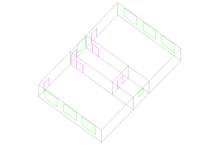
The building consists of:
1. Two 60 m² classrooms
2. One 20 m² staff office
3. One 10 m² WC
Total conditioned floor area of 150 m²
Total conditioned volume of 450 m³
The completed model combines mechanical ventilation, heat recovery, room-level heating and cooling, central heating and cooling plant, occupancy profiles and annual dynamic simulation.
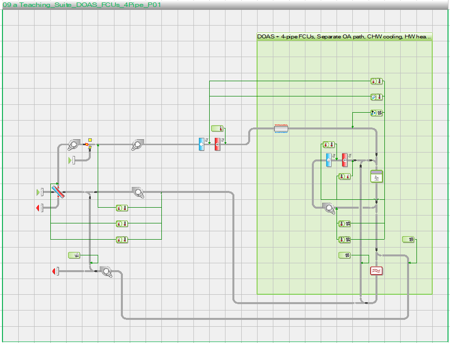
The final HVAC arrangement uses a dedicated outdoor-air system (DOAS) with sensible heat recovery together with four-pipe fan-coil units (FCUs) serving the occupied rooms.
Cooling is supplied by a water-cooled electric chiller, while heating is provided through a central hot-water system served by two boilers.
Building Model
The thermal model was developed to represent the different operational requirements of classrooms, office accommodation and sanitary spaces.
Space | Area | Volume | Design Occupancy |
|---|---|---|---|
Classroom 01 | 60 m² | 180 m³ | 31 people |
Classroom 02 | 60 m² | 180 m³ | 31 people |
Staff Office | 20 m² | 60 m³ | 2 people |
WC | 10 m² | 30 m³ | Transient occupancy |
Representative fabric properties used within the model included:
Glazing U-value: approximately 1.57 W/m²K
External doors: approximately 2.17 W/m²K
Ground floor: 0.22 W/m²K
Roof: 0.18 W/m²K
Classroom external walls: approximately 0.50 W/m²K
Office external walls: approximately 0.82 W/m²K
Infiltration: approximately 0.20 air changes per hour
Internal gains included occupant sensible and latent heat, lighting and equipment loads.
Lighting was modelled at 6 W/m², while equipment gains were modelled at 5 W/m².
HVAC System
The ApacheHVAC model separates ventilation requirements from room heating and cooling.
Dedicated Outdoor-Air System
The DOAS provides conditioned outdoor air to the classrooms and staff office. The system delivers a total design outdoor-air flow of: 670 L/s
distributed as follows:
Space | Design Outdoor Air |
|---|---|
Classroom 01 | 310 L/s |
Classroom 02 | 310 L/s |
Staff Office | 20 L/s |
WC | 0 L/s |
Total | 670 L/s |
Each classroom receives approximately 10 L/s per person of outdoor air.
A separate 30 L/s extract system serves the WC.
Sensible heat recovery is incorporated into the air-handling system to reduce the heating and cooling required to condition incoming outdoor air.
Room Heating and Cooling
Independent four-pipe fan-coil units provide room-level heating and cooling.
The occupied temperature settings are:
Heating: 21°C
Cooling: 24°C
During unoccupied periods, the model uses:
Heating setback: 16°C
Cooling setback: 28°C
The building operates primarily on weekdays, with HVAC operation beginning ahead of occupancy to allow the rooms to approach their occupied temperature conditions.
Fan-coil units respond independently to the thermal requirements of each space.
Heating and Cooling Loads
Dynamic load calculations were completed for the four modelled spaces.
Space | Peak Heating | Sensible Cooling | Total Cooling |
|---|---|---|---|
Classroom 01 | 0.569 kW | 4.954 kW | 6.222 kW |
Classroom 02 | 0.569 kW | 3.542 kW | 4.812 kW |
Staff Office | 0.050 kW | 1.086 kW | 1.133 kW |
WC | 0.051 kW | 0.000 kW | 0.000 kW |
Classroom 01 produces the highest individual cooling demand.
The combined individual room cooling peaks total approximately 12.17 kW.
The coincident system cooling demand is slightly lower at: 12.032 kW
comprising:
9.168 kW sensible cooling
2.864 kW latent cooling
The difference reflects the fact that individual room peak loads do not occur at exactly the same time.
Coincident space-heating demand is approximately: 1.485 kW
Central Plant
The completed HVAC model includes central chilled-water and hot-water systems.
Cooling Plant
The cooling system uses a: 20.62 kW water-cooled electric chiller
with approximately: 24.11 kW condenser/tower duty
The annual simulation recorded a maximum chiller load of approximately: 11.98 kW occurring on 15 August at 15:00.
Heating Plant
The heating system consists of two boilers, each rated at approximately: 11.57 kW
giving a total hot-water plant capacity of: 23.14 kW
The annual simulation recorded a maximum boiler load of approximately: 23.02 kW on 17 February at 08:00.
The maximum recorded heating-coil demand was approximately: 21.83 kW.
Ventilation Performance
Ventilation performance was assessed using the simulated mechanical outdoor-air supply and indoor CO₂ concentrations. Mechanical daily-average CO₂ concentrations remained below 1,000 ppm in the assessed spaces.
The highest reported values were approximately:
Space | Maximum Daily-Average CO₂ |
|---|---|
Classroom 01 | 843 ppm |
Classroom 02 | 843 ppm |
Staff Office | 781 ppm |
WC | 400 ppm |
The results demonstrate that the mechanical ventilation system provides the required outdoor-air service while maintaining good indoor air-quality conditions under the simulated occupancy.
Annual Energy Performance
The completed annual simulation produced the following whole-building results:
Performance Indicator | Result |
|---|---|
Conditioned floor area | 150 m² |
Site energy intensity | 227 kWh/m²·year |
Source energy intensity | 272 kWh/m²·year |
Operational carbon | 44 kgCO₂/m²·year |
Approximate annual site energy | 34,050 kWh/year |
Modelled annual energy cost | £1,445/year |
Modelled Energy Breakdown
End Use | Approximate Annual Energy |
|---|---|
Space heating | 24,765 kWh |
Cooling | 240 kWh |
Fans | 2,430 kWh |
Pumps and auxiliaries | 30 kWh |
Domestic hot water | 3,150 kWh |
Lighting | 1,875 kWh |
Equipment and other loads | 1,560 kWh |
Total | 34,050 kWh/year |
Space heating represents the largest modelled energy demand, while cooling energy use is relatively small over the annual simulation.
Dynamic Room Performance
Time-series outputs were reviewed to understand how the HVAC system responds during occupied and unoccupied periods. For Classroom 01, for example, airflow increases during the morning warm-up period, remains elevated throughout the main occupied period and then reduces progressively after normal operating hours. Winter temperature outputs show the classroom recovering towards approximately 21°C following morning HVAC start-up.
Across the occupied simulation periods, the recorded room air-temperature ranges were:
Space | Simulated Occupied Temperature Range |
|---|---|
Classroom 01 | 17.89–24.88°C |
Classroom 02 | 17.85–24.55°C |
Staff Office | 18.22–24.11°C |
The lower temperatures occur mainly around start-up periods following the unoccupied heating setback.
Thermal Comfort Assessment
Thermal comfort was reviewed using TM52, BB101 mechanical comfort criteria and ISO 7730.
TM52 Assessment
The occupied-period TM52 assessment produced a pass for all four rooms against all three TM52 criteria.
The assessment recorded:
0.0% exceedance for Criterion 1
0.0°C·h weighted exceedance for Criterion 2
0.0°C maximum exceedance for Criterion 3
Because the final building model is mechanically conditioned, the TM52 results are presented as supplementary thermal-comfort information rather than as evidence of a free-running naturally ventilated building.
BB101 Mechanical Comfort
The BB101 mechanical comfort assessment identified a limited number of occupied hours with predicted mean vote above +0.5:
Space | Hours with PMV Above +0.5 |
|---|---|
Classroom 01 | 24 hours |
Classroom 02 | 18 hours |
Staff Office | 28 hours |
WC | 7 hours |
The simulation contained approximately 1,827 mechanically conditioned occupied hours.
Indoor CO₂ performance remained within the assessed daily-average criteria.
ISO 7730
The three principal occupied rooms were also assessed using ISO 7730 thermal-comfort criteria.
Under Category C, all three assessed rooms achieved 100% of the evaluated hours within ±0.7 PMV.
Maximum predicted percentage dissatisfied values were approximately:
Classroom 01: 12.84%
Classroom 02: 12.95%
Staff Office: 12.79%
The more demanding Category B assessment was not achieved throughout the complete occupied period.
Project Outcome
The completed model demonstrates the development and simulation of a multi-zone school HVAC system within IES VE ApacheHVAC. The final model incorporates:
1. Dynamic thermal modelling
2. Room-specific occupancy and internal gains
3. Dedicated mechanical outdoor-air supply
4. Sensible heat recovery
4. Four-pipe fan-coil units
5. Independent room temperature control
6. Central chilled-water and hot-water systems
7. Chiller and boiler sizing
8. Mechanical extract ventilation
9. Annual energy simulation
10. Indoor CO₂ assessment
11. TM52 thermal-comfort screening
12. BB101 mechanical comfort assessment
13. ISO 7730 comfort assessment
14. Hourly room and HVAC performance analysis
The ApacheHVAC network completed successfully, with all modelled rooms connected to the intended HVAC system and annual simulation results generated for room conditions, airflow, heating and cooling demand, central plant operation, energy consumption and thermal comfort.
The project provides a complete example of applying building physics, dynamic thermal simulation and detailed HVAC modelling to an educational building using IES VE.
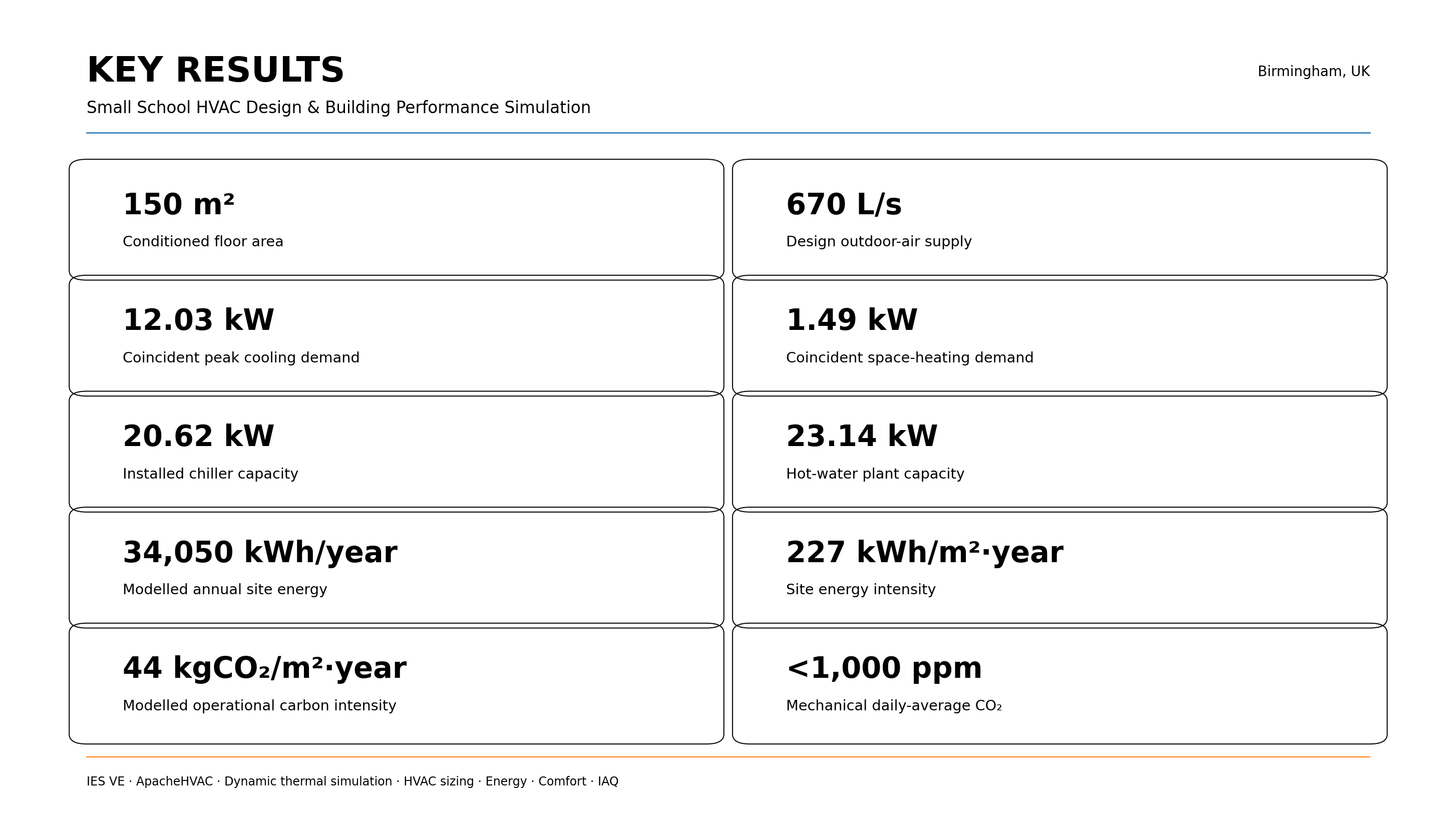
Key Results
150 m²
Conditioned floor area
670 L/s
Design outdoor-air supply
12.03 kW
Coincident peak cooling demand
1.49 kW
Coincident space-heating demand
20.62 kW
Installed chiller capacity
23.14 kW
Hot-water plant capacity
34,050 kWh/year
Modelled annual site energy
227 kWh/m²·year
Site energy intensity
44 kgCO₂/m²·year
Modelled operational carbon intensity
<1,000 ppm
Mechanical daily-average CO₂ across assessed spaces